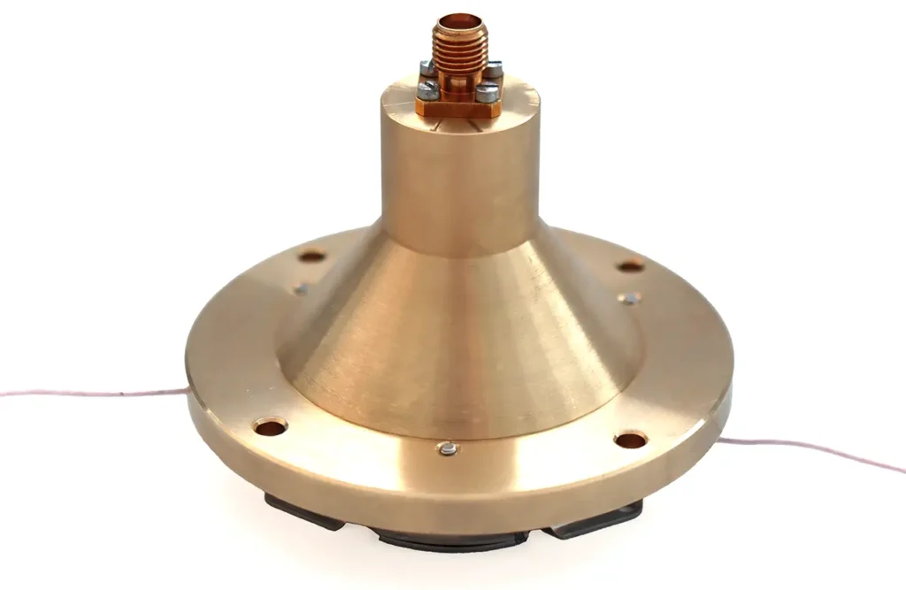
In order to ensure the most efficient transfer of the pulse arriving at the anode to the detector SMA output connector, as well as the best possible pulse reproduction, it is necessary that the resistance of the SMA – anode transmission line from the should be the most stable. Since the resistance of the SMA connectors and the input impedance of most high-speed analyzers is 50 Ω, it is essential that the detector impedance is the same. To match the amplifier input impedance, VTC “Baspik” TOF detectors use a cone-shaped anode, in which the transition from the anode active surface to the inner diameter of the wire inside the coaxial cable through the SMA connector is smooth.
Specification
The detector electrical connection diagram
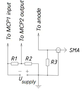
R1 = 2MΩ; R2 =300 kΩ; R3 = 100 kΩ ÷ 1 МΩ
Shape of the detector output pulse
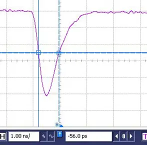
The detector with a cone anode provides an output pulse of short width without attenuated oscillations
Basic parameters
| Parameter | Value |
|---|---|
| MCP channel diameter (µm) | 10 |
| Active area diameter (mm) | 26 |
| MCP quantity | 2 |
| Pulse height (ps) (max) | 900 |
| Pulse leading edge rise time (рs) | 450 |
| Gain | 1×10⁷ |
| Pulse height resolution, % (max) | 135 |
| Count rate density (max.) (s-1×cm-2) | 3 |
| MCP voltage (kV) | 2.2 |
| MCP output–anode voltage (kV) | 0.3 |